java integer divison
· 4 min read
背景
了解java整除除法的规则
jls 描述
Integer division rounds toward 0. That is, the quotient produced for operands n
and d that are integers after binary numeric promotion (§5.6) is an integer value q
whose magnitude is as large as possible while satisfying |d ⋅ q| ≤ |n|. Moreover, q
is positive when |n| ≥ |d| and n and d have the same sign, but q is negative when
|n| ≥ |d| and n and d have opposite signs.
也就是
int res = 3 / 5 = 0 ;
最后使用的bytecode 是idiv
我们看看idiv 这个bytecode 是怎么实现的吧:
jvm 实现
void Assembler::idivl(Register src) {
  int encode = prefix_and_encode(src->encoding());
  emit_int16((unsigned char)0xF7, (0xF8 | encode));
}

void Assembler::divl(Register src) { // Unsigned
  int encode = prefix_and_encode(src->encoding());
  emit_int16((unsigned char)0xF7, (0xF0 | encode));
}
查看intel的文档:

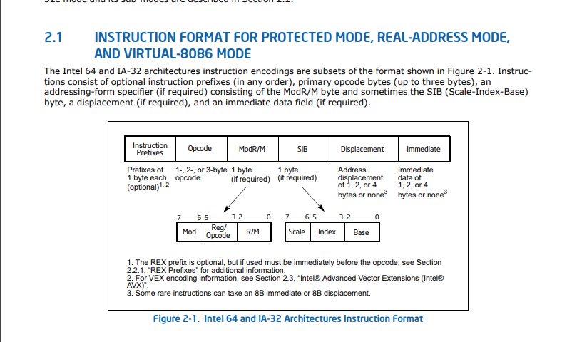
2.1.5 Addressing-Mode Encoding of ModR/M and SIB Bytes
The values and corresponding addressing forms of the ModR/M and SIB bytes are shown in Table 2-1 through Table
2-3: 16-bit addressing forms specified by the ModR/M byte are in Table 2-1 and 32-bit addressing forms are in
Table 2-2. Table 2-3 shows 32-bit addressing forms specified by the SIB byte. In cases where the reg/opcode field
in the ModR/M byte represents an extended opcode, valid encodings are shown in Appendix B.
In Table 2-1 and Table 2-2, the Effective Address column lists 32 effective addresses that can be assigned to the
first operand of an instruction by using the Mod and R/M fields of the ModR/M byte. The first 24 options provide
ways of specifying a memory location; the last eight (Mod = 11B) provide ways of specifying general-purpose, MMX
technology and XMM registers.
The Mod and R/M columns in Table 2-1 and Table 2-2 give the binary encodings of the Mod and R/M fields required
to obtain the effective address listed in the first column. For example: see the row indicated by Mod = 11B, R/M =
000B. The row identifies the general-purpose registers EAX, AX or AL; MMX technology register MM0; or XMM
register XMM0. The register used is determined by the opcode byte and the operand-size attribute.
Now look at the seventh row in either table (labeled “REG =”). This row specifies the use of the 3-bit Reg/Opcode
field when the field is used to give the location of a second operand. The second operand must be a generalpurpose, MMX technology, or XMM register. Rows one through five list the registers that may correspond to the
value in the table. Again, the register used is determined by the opcode byte along with the operand-size attribute.
If the instruction does not require a second operand, then the Reg/Opcode field may be used as an opcode extension. This use is represented by the sixth row in the tables (labeled “/digit (Opcode)”). Note that values in row six
are represented in decimal form.
The body of Table 2-1 and Table 2-2 (under the label “Value of ModR/M Byte (in Hexadecimal)”) contains a 32 by
8 array that presents all of 256 values of the ModR/M byte (in hexadecimal). Bits 3, 4 and 5 are specified by the
column of the table in which a byte resides. The row specifies bits 0, 1 and 2; and bits 6 and 7. The figure below
demonstrates interpretation of one table value.
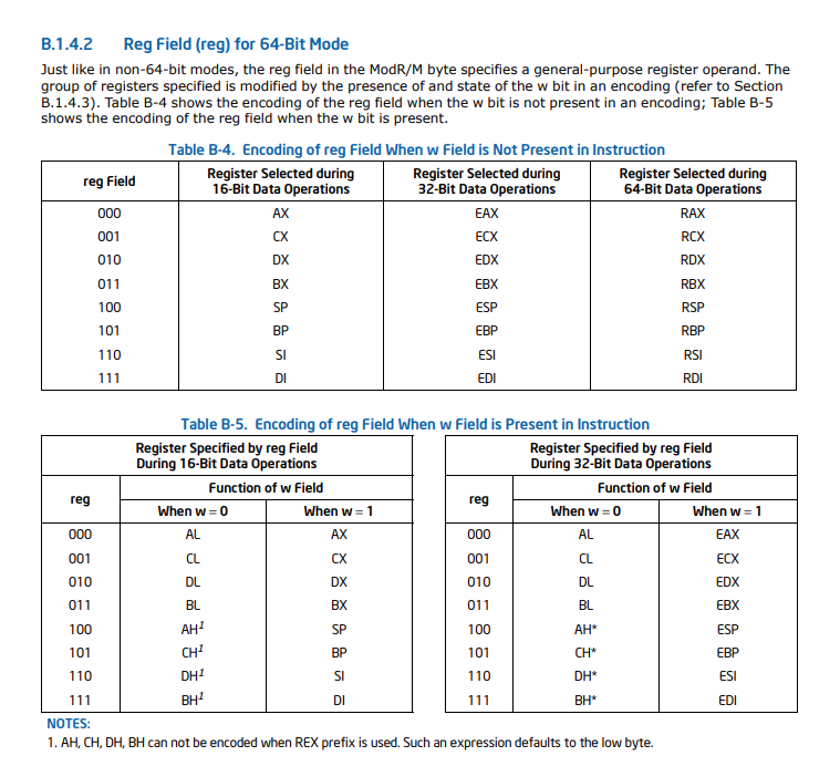
 寄存器会从0编码到16,编码顺序如上述所示
例子
int main(void){
     int num0 = 5;
     int num1 = 2;
     int num = num0 / num1 ;
     return num;
}
## 编译
gcc -O0  test.c  -o  test

## 用objdump 列出汇编内容
objdump -d  test  | grep -A20   '<main>:'
结果为
0000000000001129 <main>:
    1129:       f3 0f 1e fa             endbr64
    112d:       55                      push   %rbp
    112e:       48 89 e5                mov    %rsp,%rbp
    1131:       c7 45 f4 05 00 00 00    movl   $0x5,-0xc(%rbp)
    1138:       c7 45 f8 02 00 00 00    movl   $0x2,-0x8(%rbp)
    113f:       8b 45 f4                mov    -0xc(%rbp),%eax
    1142:       99                      cltd
    1143:       f7 7d f8                idivl  -0x8(%rbp)
    1146:       89 45 fc                mov    %eax,-0x4(%rbp)
    1149:       8b 45 fc                mov    -0x4(%rbp),%eax
    114c:       5d                      pop    %rbp
    114d:       c3                      retq
    114e:       66 90                   xchg   %ax,%ax